Assembly and installation of refrigeration unit
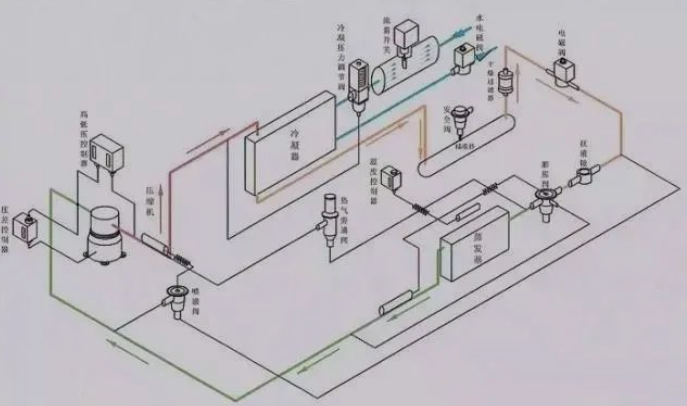
1. Both semi-hermetic or fully-closed compressors should be equipped with an oil separator, and an appropriate amount of oil should be added to the oil. When the evaporation temperature is lower than -15 degrees, a gas-liquid separator should be installed and an appropriate amount of refrigeration oil should be installed.
2. The compressor base should be installed with a shock-absorbing rubber seat.
3. There should be maintenance space for the installation of the unit, which is easy to observe the adjustment of instruments and valves.
4. The high pressure gauge should be installed at the tee of the liquid storage valve.
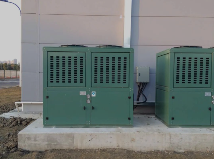
5. The overall layout of the unit is reasonable, the color is consistent, and the installation structure of each type of unit should be consistent.

Second, the installation of the cooling fan in the warehouse
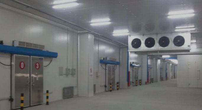
1. When choosing the position of the lifting point, first consider the best position for air circulation, and secondly consider the direction of the structure of the library body.
2. The gap between the air cooler and the library board should be greater than the thickness of the air cooler.
3. All suspenders of the air cooler should be tightened, and the bolts and suspenders should be perforated and sealed with sealant to prevent cold bridges and air leakage.
4. When the ceiling fan is too heavy, the No. 4 or No. 5 angle iron should be used as the beam, and the lintel should be spanned to another roof plate and wall plate to reduce the load-bearing.

Refrigeration pipeline installation technology
1. The diameter of the copper pipe should be selected strictly according to the suction and exhaust valve interface of the compressor. When the separation between the condenser and the compressor exceeds 3 meters, the diameter of the pipe should be increased.
2. Keep a distance of more than 400mm between the suction surface of the condenser and the wall, and keep a distance of more than 3 meters between the air outlet and obstacles.
3. The diameter of the inlet and outlet pipes of the liquid storage tank is based on the exhaust and liquid outlet pipe diameters marked on the unit sample.
4. The suction line of the compressor and the return line of the air cooler shall not be smaller than the size indicated in the sample to reduce the internal resistance of the evaporation line.
5. The exhaust pipe and return pipe should have a certain slope. When the position of the condenser is higher than that of the compressor, the exhaust pipe should be sloped towards the condenser and a liquid ring should be installed at the exhaust port of the compressor to prevent the gas from cooling and liquefying backflow after shutdown. To the high pressure exhaust port, it will cause liquid compression when the machine is restarted.
6. A U-shaped bend should be installed at the outlet of the air return pipe of the air cooler, and the air return pipe should be sloped toward the compressor to ensure smooth oil return.
7. The expansion valve should be installed as close to the air cooler as possible, the solenoid valve should be installed horizontally, the valve body should be vertical and pay attention to the direction of liquid discharge.
8. If necessary, install a filter on the return line of the compressor to prevent the dirt in the system from entering the compressor and remove the water in the system.
9. Before all sodium and lock nuts of the refrigeration system are fastened, lubricate with refrigeration oil to strengthen the sealing, wipe clean after fastening, and lock the packing of each section door.
10. The temperature sensing package of the expansion valve is fastened with a metal clip at 100mm-200mm from the outlet of the evaporator, and wrapped with double-layer insulation.
11. After the welding of the whole system is completed, the air tightness test shall be carried out, and the high pressure end shall be filled with nitrogen 1.8MP. The low-pressure end is filled with nitrogen 1.2MP, and soapy water is used for leak detection during the pressurization period, and each welding joint, flange and valve are carefully checked, and the pressure is maintained for 24 hours after the leak detection is completed.

Installation technology of electronic control system
1. Mark the wire number of each contact for maintenance.
2. Make the electric control box in strict accordance with the requirements of the drawings, and connect the power to do the no-load experiment.
3. Mark the name on each contactor.
4. Fix the wires of each electrical component with wire ties.
5. The electrical contacts are pressed against the wire connectors, and the motor main line connectors should be clamped with wire cards.
6. Line pipes should be laid for each equipment connection and fixed with clips. When connecting PVC line pipes, glue should be used, and the nozzles should be sealed with tape.
7. The distribution box is installed horizontally and vertically, the ambient lighting is good, and the room is dry for easy observation and operation.
8. The area occupied by the wire in the line pipe shall not exceed 50%.
9. The selection of wires must have a safety factor, and the temperature of the wire surface should not exceed 4 degrees when the unit is running or defrosting.
10. The wires should not be exposed to the open air, so as to avoid long-term sun and wind, the aging of the wire skin, and the occurrence of short-circuit leakage and other phenomena.
Leak testing of refrigeration systems
The tightness of the refrigeration system is usually an important indicator to measure the installation or manufacturing quality of the refrigeration device, because system leakage not only causes refrigerant leakage or outside air infiltration, which affects the normal operation of the refrigeration device, but also causes economic losses and pollutes the environment.
For large refrigeration systems, due to the large number of welding points and connectors in the process of installation or assembly, leakage is inevitable, which requires the commissioning personnel to carefully test the system for leaks to detect and eliminate each leak point. The system leak test is the main item in the whole debugging work, and it must be carried out seriously, responsibly, meticulously and patiently.
Fluoridation debugging of refrigeration system
1. Measure the power supply voltage.
2. Measure the resistance of three windings of the compressor and the insulation of the motor.
3. Check the opening and closing of each valve of the refrigeration system.
4. After evacuation, pour refrigerant into the storage liquid to 70%-80% of the standard charging volume, and then run the compressor to add gas from low pressure to enough volume.
5. After starting the machine, first listen to whether the sound of the compressor is normal, check whether the condenser and air cooler are running normally, and whether the three-phase current of the compressor is stable.
6. After normal cooling, check all parts of the refrigeration system, exhaust pressure, suction pressure, exhaust temperature, suction temperature, motor temperature, crankcase temperature, temperature before expansion valve, and observe the frosting of evaporator and expansion valve. Observe the oil level and color change of the oil mirror, and whether the sound of the equipment is abnormal.
7. Set the temperature parameters and the opening degree of the expansion valve according to the frosting and usage conditions of the cold storage.
Matters needing attention during the test machine
1. Check whether each valve in the refrigeration system is in a normal open state, especially the exhaust shut-off valve, do not close it.
2. Open the cooling water valve of the condenser. If it is an air-cooled condenser, the fan should be turned on. Check that the turning water volume and air volume should meet the requirements.
3. The electrical control circuit should be tested separately in advance, and attention should be paid to whether the power supply voltage is normal before starting.
4. Whether the oil level of the compressor crankcase is in a normal position, it should generally be kept at the horizontal centerline of the sight glass.
5. Start the refrigeration compressor to check whether it is normal and whether the rotation direction is correct.
6. When the compressor is started, check whether the indicated values of the high and low pressure gauges are within the pressure range for the normal operation of the compressor.
7. Check the indication value of the oil pressure gauge. For the compressor with energy unloading device, the oil pressure indication value should be 0.15-0.3MPa higher than the suction pressure. For the compressor without the unloading device, the oil pressure indication value is 0.05 higher than the suction pressure. -0.15MPa, otherwise the oil pressure should be adjusted.
8. Listen to the expansion valve for the sound of refrigerant flowing, and observe whether there is normal condensation (air conditioner) and frost (cold storage) in the pipeline behind the expansion valve.
9. The compressor with energy unloading should work at full load in the early stage of operation. This can be understood according to the temperature of the cylinder head by hand. If the temperature of the cylinder head is high, the cylinder is working, and the temperature of the cylinder head is low, the cylinder has been unloaded. When the unloading test is carried out, the motor current should drop significantly.
10. Safety protection devices installed in the refrigeration system, such as high and low pressure relays, oil pressure. Poor relay, cooling water and chilled water cut-off relay, chilled water freezing protection relay and safety valve and other equipment, their actions should be identified during the commissioning stage to avoid malfunction or non-action.
11. Check whether the indication values of other various instruments are within the specified range. If there is an abnormal situation, stop the machine immediately for inspection.
12. The common failure during the debugging of the refrigeration system is the blockage of the expansion valve or the drying filter (especially the medium and small Freon refrigeration units).
13. The main reason for the blockage is that the garbage and water in the system have not been cleaned up, or the water content of the charged Freon refrigerant does not meet the standard.
Post time: Feb-24-2022


